By: Jay Perkins, P.E. and Ken Smith (MD&B)
For trenchless installations below railroads, having complete and accurate subsurface information is key to ensuring the excavation doesn’t damage the critical infrastructure above. Knowing ground conditions across the entire installation means you don’t encounter problems that could slow or endanger the dig.
Brierley Associates was retained by the project Lead Design Professional, Kleinfelder, to serve as tunneling technical advisor for a new stormwater culvert for the City of Dover, NH. The alignment for the new 84-inch Reinforced Concrete Pipe (RCP) culvert was planned to go though an embankment that supports three active rail lines operated by PanAm. To install the 230-foot-long pipe, an 84-in diameter hydraulically pushed jacking shield with hand excavating was the chosen method.
Prior geotechnical investigations during the 2003-2004 time frame consisted of four borings terminated about 5 feet below the planned pipe invert. Locations of the borings were at the Launch and Receiving pits and the top of the embankment. Given the relatively steep embankment grade of 1H:1V and the short distance of approximately 70 feet between the launch shaft and top of embankment where two of the borings were drilled, no borings were completed on the embankment slopes. In general, the exploration program revealed about 5 to 45 feet of soil cover above the planned crown of the new culvert. Those soils consisted of loose to medium dense sand and gravel Fill material overlying Glacial Till. The Glacial Till consisted of well graded sand and gravel within a very stiff to hard silt matrix. The static groundwater level was recorded at the proposed pipe crown at the launch shaft and dropping to just below invert at the receiving end where the invert daylighted at the ground surface. Bedrock was not encountered at any of the boring locations.
During installation of steel sheeting for the support of excavation system for the launch shaft, bedrock was encountered at the launch side of the shaft about 4 feet above the proposed pipe invert. A supplemental subsurface investigation in the form of borings and probes disclosed a small pinnacle of rock within the alignment below the embankment. The rock was classified as hard, brittle metamorphosed Sandstone with an average Unconfined Compressive Strength of 17.0 ksi. It was estimated that almost 100 CY of rock would need to be removed to allow for the jacking shield advancement. Although rock removal within the launch shaft was accomplished by use of a hydraulic hammer, production was very slow. That challenge, combined with the anticipated inaccessibility of equipment and working at the face of the jacking shield, would prove an extremely difficult and inefficient method for rock excavation. To complicate the operation, the railroad embankment is comprised of loose fill material at a very steep grade.
Rock Removal Challenges and Solution
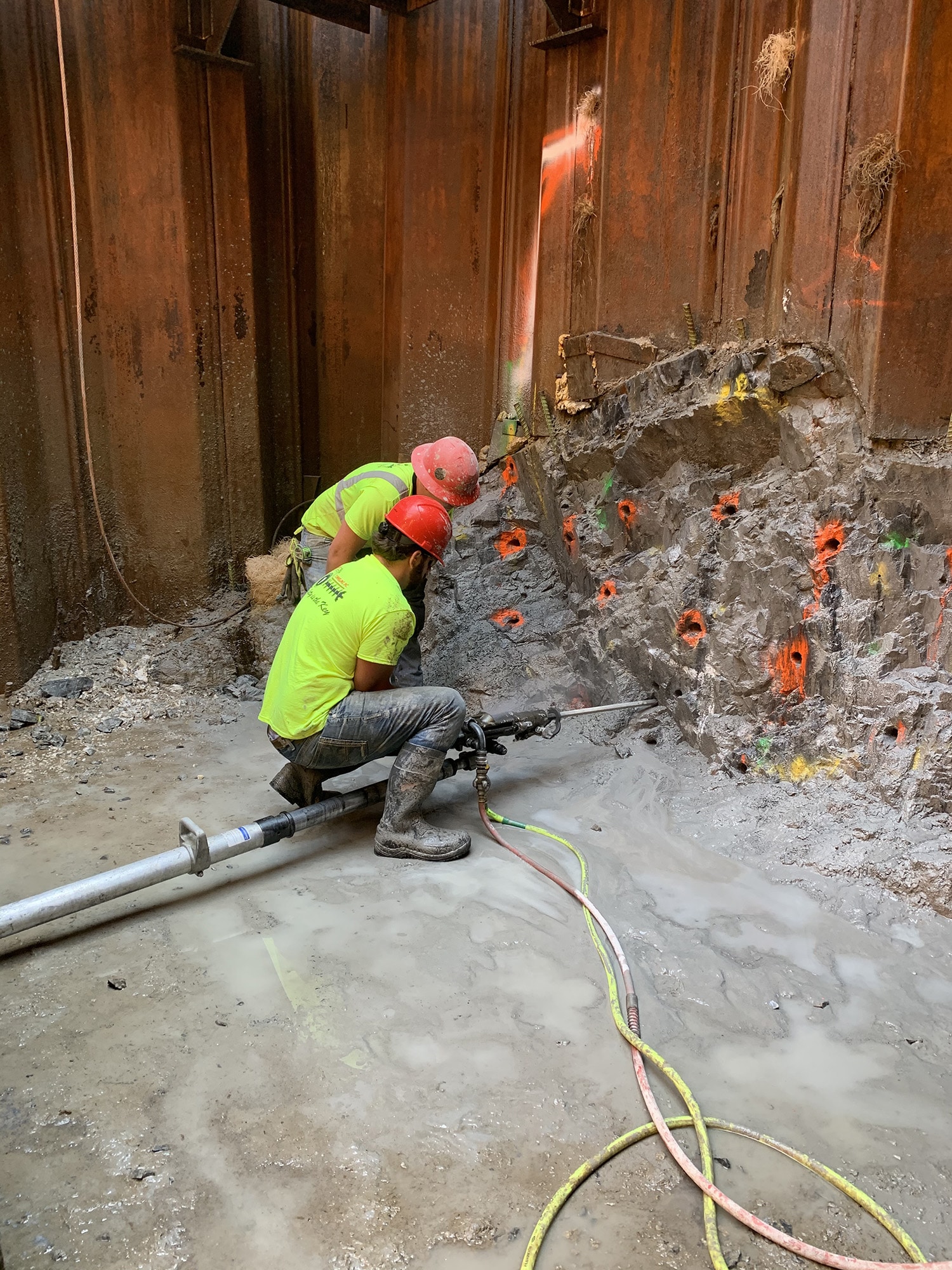
Due to concerns related to the loose nature of the embankment fill and vibrations, Brierley’s Jay Perkins assessed the Contractor’s proposed use of mechanical drilling and chemical splitting to break and remove the rock. Although mechanical means combined with non-explosive demolition agents, such as Ecobust and Dexpan products could reduce ground and air vibrations, flyrock and dust or gas compared with conventional blasting techniques it became apparent these methods were inefficient and extremely difficult to deploy at the working face of the jacking shield. This led to reconsidering some form of blasting, provided a scaled-down version to conventional blasting could be designed.
To come up with a workable solution Brierley Associates collaborated with Maine Drilling & Blasting (MD&B) to develop a rock removal method by “Micro-fracture.” Micro-fracture blast designs have been developed by MD&B and successfully used on numerous projects within vibration hypersensitive environments. Based on a scaled-down application of conventional rock fragmentation methodology the blast design significantly localizes the fracturing effect to the geology and associated ground and air response. Advanced electronic initiation control systems are key to successful “Micro-fracturing”. These systems allows the delay interval to match a scaled spatial distribution with an equally scaled charge. This miniaturized design measures charge weight in ounces rather than pounds, and spatial distribution measured in inches rather than feet. The electronic initiation allows the charge interval to be precisely programmed to as low as 1ms. The electronic initiation is also configured to sequence horizontally, and vertically by decking, within each hole to provide 3D control of fracture expansion. In place of conventional explosives and blasting agents, this technology uses a high density, high energy and high velocity charge that is uniformly distributed within the geology to be fragmented.
The “Micro-fracturing” design to facilitate removal of rock within the tunnel alignment called for 1-3/4-inch diameter holes drilled at 12 to 24-inch burden and hole spacing and 3 to 5 feet deep, using between 5 and 13 ounces per delay of decked high explosive cast boosters with electronic initiation. The number of loaded holes per shot varied from 4 to 34 with an average of about 26 holes. Resulting powder factors ranged from approximately 0.8 to 1.3 lbs./cy. Nine unloaded closely spaced cut holes drilled in a 3 by 3 pattern were used to create a second free face generally at the center of the shot.
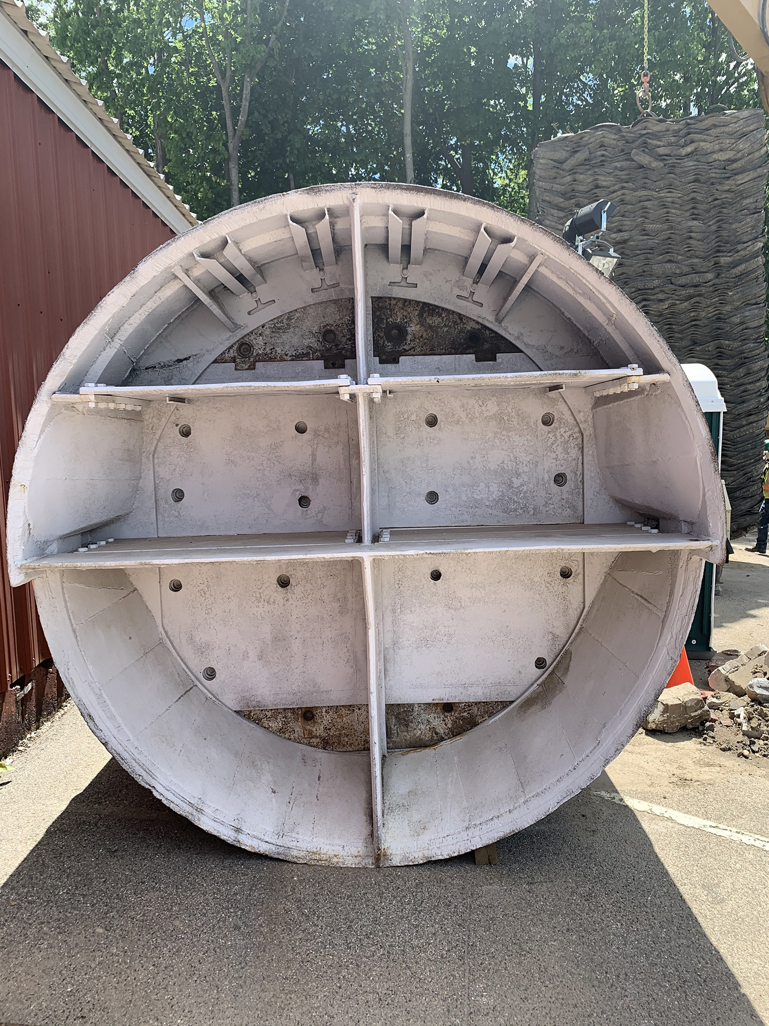
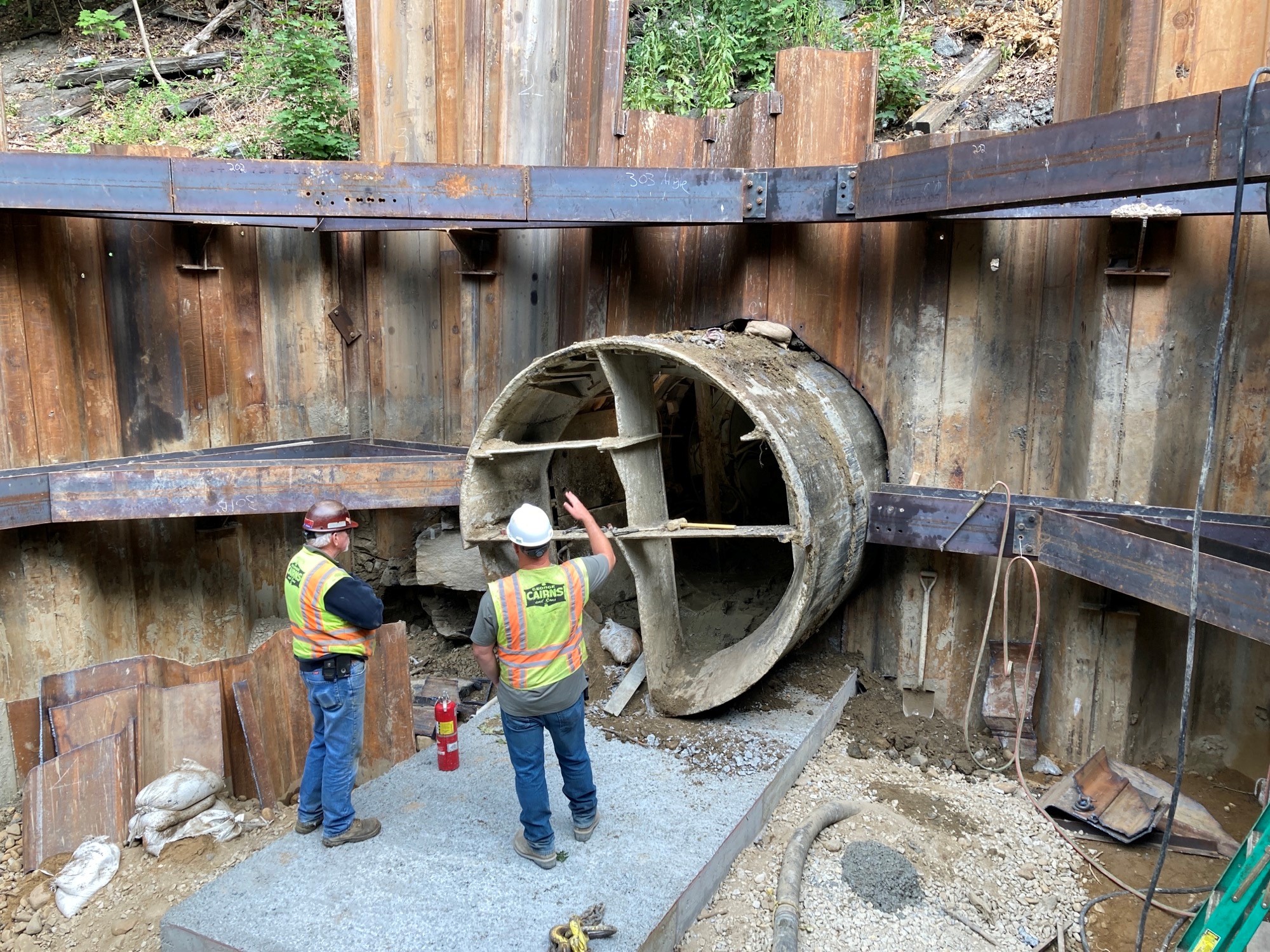
Activities at the face included soil stabilization, drilling and loading the blast holes and mucking the rock and overburden soil for the estimated first 50 feet of tunnel where the rock was present. With the limited space for completing these activities at the face of the jacking shield with the presence of breast plates, it was decided to use an oversized and open face liner plate tunnel system to provide for more working space. Once through the rock, the jacking shield was then telescoped thru the liner plate system, and the remainder of the tunnel hand-mined within the jacking shield to completion. A 10-ft diameter liner plate system was designed by Brierley and installed by Turn-Key Tunneling (TKT) of Columbus, Ohio.
Using the Micro-fracture designs with mixed-face conditions, still posed concerns about the overlying soil collapsing into the blasted face. To mitigate this issue, the overburden soils were treated at the face and below the embankment before blasting with a cement grout, and chemical stabilization with an acrylic resin product that once cured formed the soil/chemical mix to a jell-like consistency. Also, cement grout was pumped through ports in the liner plate to fill voids that might have formed behind the liner plates during Micro-fracturing.
Geotechnical instrumentation to monitor potential embankment displacements was another important aspect of this project. An array of settlement monitoring points was installed at the ground surface and measured after each blast. Ground and air vibrations were recorded at the nearest buildings and railroad tracks at approximately 50 to 70 feet from the blasting. Peak particle velocities and air overpressures were generally less than 0.3 in/sec and 135 dBL, respectively. With the presence of the loose fill material overlying the natural deposits, blast vibration frequencies were relatively low at an average of 13 Hz.
Rock removal to allow tunnel advancement and installation of the new stormwater drainage culvert was successful, without compromising the stability of the railroad embankment, for these main reasons:
1) Open communication with all stakeholders
2) Test blasts demonstrated effective rock fracturing without exceeding vibration and air overpressure thresholds.
3) Using the test blast data to “dial-in” the Micro-fracture blast designs for the mixed face conditions, and
4) The presence of the very stiff to hard glacial till deposit that responded very predictably to blasting and had a very good stand up time.
5) Geotechnical instrumentation program to document embankment behavior
However, the obvious lesson learned was as every Geotechnical Engineer would say, “for every project you can never have too many test borings”.
Project Team:
Project Engineer: Kleinfelder
Trenchless Installation Design: Brierley Associates
Liner Plate System Installation: Turn-Key Tunneling (TKT)
General Contractor: George Cairns and Sons
Microfracture Blasting Contractor: Maine Drilling & Blasting
Pipe Jacking Subcontractor: M&P Pipe