By Kurt Breitenbucher, PE, and Bridgette Hassett, PE, GE
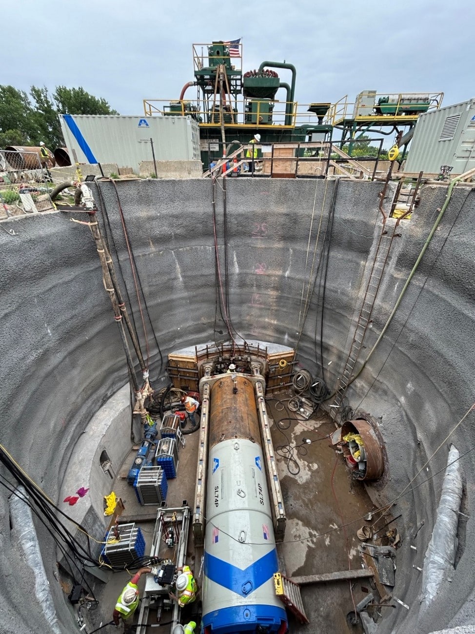
When the Metropolitan Council Environmental Services (MCES) set out to build a new gravity sewer as part of a major realignment in the Twin Cities metro, the team expected a straightforward microtunneling project. What they encountered instead was a complex puzzle involving geology, groundwater, tight construction spaces, and shaft shapes that defied convention. The solution ultimately required creativity, advanced modeling, and a construction approach that blended precision with speed. The contractor, Engineering and Construction Innovations (ECI), brought in Brierley Associates to design the support of excavation (SOE) systems needed for the shafts that would launch and receive the microtunneling equipment.
The ECI team re‑imagined shaft design to deliver a project beneath one of Minnesota’s busiest highways.
 A Project Defined by Constraints
The Oakdale Gravity Sewer project extends approximately 3,800 feet through the eastern Twin Cities, with one reach paralleling Interstate 94 and another tunneling directly beneath it. Early geotechnical findings quickly challenged expectations. Initial borings suggested clean soils with few cobbles, but larger-diameter test holes told a different story: angular cobbles and boulders were widespread, complicating excavation and limiting viable SOE options. These materials were embedded in a matrix of silty sands—difficult enough to manage on their own, especially with groundwater perched across much of the alignment.
Given these conditions, traditional systems like sheet piling or soldier piles weren’t workable. The soils were too coarse for sheet piles to drive effectively, and over‑drilling soldier piles would still require significant dewatering. More sophisticated systems such as secant piles or slurry walls were judged too complex and too costly for temporary work.
The team needed another path.
Choosing the Shape of Success
The project required three shafts, one circular working shaft, 30 feet in diameter and 33 feet deep, and two elliptical shafts, each 25 by 35 feet and approximately 44 feet deep.
The circular shaft posed few issues. Its geometry naturally resists earth pressure and is common in deep excavation work. But the elliptical shafts were a departure from standard practice.
Their shape wasn’t chosen for aesthetics. The shafts had to avoid existing utilities, nearby structures, and the interstate itself, all within a tight construction corridor. The ellipse made it possible to fit the needed volume within the available footprint.
To build these shafts safely and efficiently, the team turned to a sequential top‑down technique, spraying shotcrete and installing lattice girders and reinforcing mesh as they advanced downward. This method allowed excavation and support to occur in tight cycles—ideal for rapid construction but challenging from a design perspective, especially given the non‑uniform geometry.
Modeling a Shape That Doesn’t Behave Like a Cylinder
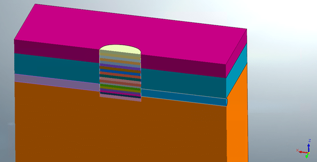
Understanding how an elliptical shaft deforms under load required advanced modeling. Brierley staff built a detailed 3D finite element model using MIDAS FEA NX, simplifying the soil profile into three layers of medium‑dense to dense silty sands and assuming Mohr‑Coulomb material behavior.
Initial analysis produced troubling results: even five‑foot excavation lifts produced unrealistic wall deformations, in part because the soil’s effective cohesion was initially modeled as zero. By incorporating reasonable cohesion values—based on fines content and apparent cohesion due to short‑term desiccation—the team improved the model’s behavior. A parametric study suggested that 250 psf of cohesion offered the most realistic representation.
Yet even with smaller 2.5‑foot lifts, the model predicted exaggerated bottom heave and inward wall movements, likely artifacts of the constitutive soil model. While the MIDAS model provided valuable insight into general behavior—especially how the long axis of the ellipse tended to “squeeze” inward—it diverged too far from observed reality to be used as the sole design method.
The team supplemented the analysis. Using RISA‑3D, the team created a discrete structural model supported by soil springs. By tuning spring stiffnesses to match expected deflection ranges, they validated the design using thrust‑moment interaction checks. This model aligned much more closely with engineering judgment and provided confidence that the shotcrete shell could safely withstand the loads.
Building Underground, Fast
Construction moved rapidly, with excavation, mucking, reinforcing, and shotcreting occurring continuously within each lift. The pace made traditional monitoring methods impractical. Inclinometers would capture movement in only one plane, extensometers might miss deformation entirely depending on placement, and survey checkpoints required more time than the tight cycles allowed.
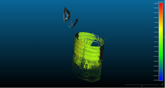
Instead, the team adopted a modern solution: LiDAR scanning from inside the shafts. The scans captured 3D geometry at high resolution, allowing the team to compare as‑built shapes against predicted deformation patterns.
The results were encouraging.
Most of the shaft walls showed slight inward movement, consistent with expected soil–structure interaction. One vertical seam displayed a small outward bulge—exactly where lattice girder butt‑plates aligned—matching predictions based on simple structural behavior.
This real‑world confirmation reinforced the design’s reliability and demonstrated the value of using reality‑capture technology in temporary works.
By the time excavation wrapped up in January 2025, the shafts had performed well. No cracking or significant deformation occurred, and tunnel drives were completed successfully later that year.
The Oakdale Gravity Sewer shaft design demonstrates how engineering teams can innovate within the constraints of tight spaces, challenging ground conditions, and aggressive schedules. By embracing unconventional shaft geometry, modern modeling techniques, and LiDAR‑based monitoring, the project team not only delivered a successful system but also developed insights that will improve future designs.
It’s a reminder that underground construction is as much about adaptation as it is about calculation. Sometimes the most effective solutions come from reshaping expectations—quite literally.